Session 2
Introduction
Welcome to session 2 of our ROS2 Basics labs! Today, we will be exploring the visualization and simulation tools integrated with ROS2. In this session, we will dive into Rviz, Transforms (TFs), launch files, URDF, Xacro, and Gazebo, building the essential skills for designing and simulating robotic systems.
Our main goal for today is to create a model of the Thymio robot that is fully integrated with ROS2 and capable of smooth operation in Gazebo simulation. We will guide you step by step through the essential elements needed to achieve this. You will begin with simple examples to introduce each concept and gradually apply this knowledge to build the Thymio model. Now, let’s get to work!
URDF Tutorial Example
In this first part of the session, we will start by exploring Rviz, a 3D visualization tool, and TFs (transform frames), which are essential for managing coordinate frames in ROS2. We will use an example URDF (Unified Robot Description Format) model to learn how to visualize and interact with a robot model in Rviz. Do not worry if these concepts do not fully make sense yet, we will go through each of them step by step throughout today’s session.
Let’s get started by ensuring that everything we need is installed and set up. The first step is to install the urdf_tutorial package. This package is not part of the default ROS2 installation, so let’s install it now.
Open a terminal and run:
sudo apt install ros-humble-urdf-tutorial && source /opt/ros/humble/setup.bash
Note
If you have been paying attention to the terminal messages, you may have noticed that this package is already installed in the Docker environment. Due to time considerations, we have not covered all the steps of the installation process. However, the following outlines the general procedure you can follow to install any new package in ROS2.
Step |
Task |
Command |
|---|---|---|
1 |
Update your package list |
|
2 |
Upgrade existing packages |
|
3 |
Install the desired package |
|
4 |
Source the ROS2 setup file |
|
5 |
Verify the package installation |
|
Let’s check where this package and others are installed:
cd /opt/ros/humble/share && ls
Navigate to the URDF folder of the urdf_tutorial package and check its content:
cd /opt/ros/humble/share/urdf_tutorial/urdf && ls
Among the files listed, you will see 08-macroed.urdf.xacro, which is the example we will use now.
Launch the example:
ros2 launch urdf_tutorial display.launch.py model:=/opt/ros/humble/share/urdf_tutorial/urdf/08-macroed.urdf.xacro
Now that Rviz is running and the robot model is loaded, let’s take a moment to explore what Rviz offers and why it is such a valuable tool in the ROS2 ecosystem. Visualizing the robot in a 3D environment provides an intuitive way to understand its structure, relationships, and interactions.
In particular, Rviz allows you to visualize:
Robot models: These are detailed representations of the robot’s physical structure.
Transform frames (TFs): Coordinate frames that define the spatial relationships between different parts of the robot, essential for motion and interaction.
Sensors data: Information from sensors such as LiDAR, cameras, or depth sensors, displayed in real-time to help interpret the robot’s environment.
As you can see in the image below, Rviz offers a variety of default plugins that enable you to monitor different aspects of your system. These plugins can be accessed and added to your workspace by clicking the Add button in the Rviz interface.

Rviz also allows you to interact with tools like the Joint State Publisher (the second pop-up window), a GUI that lets you manipulate the robot’s joints. This enables you to see how joint movements affect the robot’s structure.
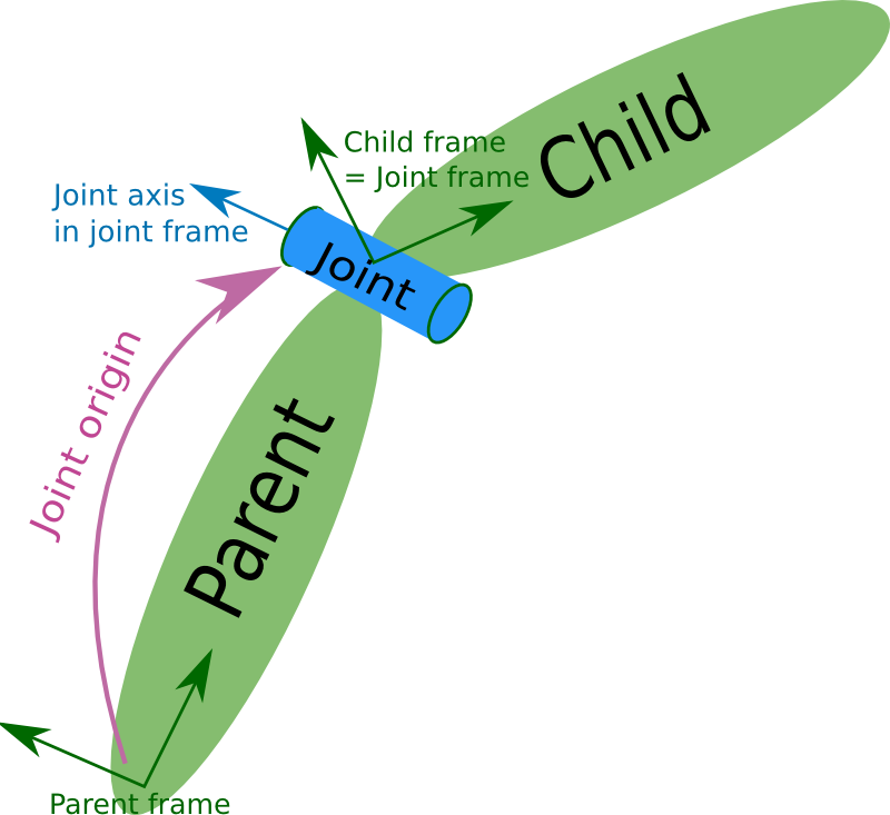
A key question to consider here is: How does ROS2 determine the positions and movements of the different links relative to one another over time?
The answer lies in Transform Frames (TFs). These frames represent the spatial relationships (positions and orientations) between the robot’s parts and its environment. TFs enable ROS2 to continuously track how each part of the robot moves in relation to others. By maintaining structured relationships between frames, TFs play a crucial role in various robotic tasks.
Each frame has three axes: x (red), y (green), and z (blue), representing its orientation in 3D space. If you uncheck the RobotModel in Rviz, you can see that the TFs form a tree-like structure, showing how the robot’s rigid parts are connected.
To better visualize the TF hierarchy, you can use the view_frames tool provided by the tf2_tools package. Open a terminal and run:
cd ~/ros2_basics_ws/
ros2 run tf2_tools view_frames
After about five seconds, a PDF will be generated in your workspace. This file provides a clear tree structure of the robot’s TFs. The base_link is the root of the TF tree, and all other frames are connected as branches. Each branch connects a parent link to a child link, meaning that if the parent link moves, the child link will move accordingly.
Now that you understand the purpose of TFs, you can experiment in Rviz to see how they work alongside the RobotModel. Start by focusing on the RobotModel:
Hide TFs and explore the
RobotModelby displaying all links or only a few.Adjust joints using the Joint State Publisher and observe changes.
Next, enable the TFs and hide the RobotModel to focus on the transform frames:
Display all or specific frames to examine their relationships.
Observe how frames update dynamically with joint adjustments.
By now, you should have a foundational understanding of Rviz and TFs. Here’s a quick recap:
Rviz is a visualization tool that helps display robot models, TFs, and many other essential elements .
TFs are essential for representing spatial relationships and movement between different parts of the robot.
These tools are invaluable for building and visualizing robot models in ROS2.
Let’s keep going! In the next chapters, we will dive deeper into understanding and working with URDF files to create our own robot model.
Launch Files Overview
At this stage, you have already visualized a robot model in Rviz using the following command:
ros2 launch urdf_tutorial display.launch.py model:=<path_to_urdf>
You might have been wondering, what does the launch command do? Simply put, it runs a launch file. A launch file is a configuration file that allows you to start multiple nodes simultaneously, often with specific parameters or remapping. This is especially useful when managing complex setups, as launching multiple nodes manually from different terminals can quickly become difficult to manage.
Launch files provide a structured way to:
Start multiple nodes simultaneously
Apply specific parameters
Remap topics and services
Load additional configurations
Launch files can be written in Python, XML, or YAML. For simplicity and conciseness, we will use the XML format in this course.
Action Required
Please Download the thymio_description package required for this session and place it in the /src directory of your ros2_basics_ws workspace.
Note
Following a common convention, a robot’s model is typically stored in a package named <robot_name>_description, which organizes related files into structured folders. In our case, the thymio_description package contains several folders (launch, rviz, urdf, and worlds) that will be gradually filled with additional content as we progress.
Keep in mind that when new folders are added to a package, they are not automatically recognized by ROS2. To make them accessible, they must be installed in the package’s /share directory. If you check the setup.py file, you will notice that this step has already been handled for you.
Let’s revisit an example from Session 1, illustrated in the image below, to better understand launch files. This time, instead of manually starting each node, we will use a launch file to simultaneously launch four nodes with their appropriate configurations.

Open the file example.launch.xml
Navigate to the /thymio_description/launch folder and open the example.launch.xml file.
Add the following code to the file
<launch>
    <node pkg="demo_nodes_py" exec="talker" name="stress">
        <remap from="chatter" to="exams"/>
    </node>

    <node pkg="demo_nodes_py" exec="talker" name="BA1_students">
        <remap from="chatter" to="exams"/>
    </node>

    <node pkg="demo_nodes_py" exec="listener" name="BA2">
        <remap from="chatter" to="exams"/>
    </node>

    <node pkg="demo_nodes_py" exec="listener" name="MAN">
        <remap from="chatter" to="exams"/>
    </node>
</launch>
Question
What are the essential elements of a launch file?
Build and source the package
cd ~/ros2_basics_ws/
colcon build --packages-select thymio_description
source install/setup.bash
Run the launch file
ros2 launch thymio_description example.launch.xml
Visualize the result
rqt_graph
Note
Using a launch file, you have successfully started multiple nodes with a single command. Additionally, remapping topics has become significantly more convenient.
To save time during this class, we will not go over the creation of the launch files required for this session, as they are more advanced than the basic example we have just seen. Instead, the necessary launch files are already prepared and included in the thymio_description package. But don’t despair! We will revisit and analyze these files in detail during Preparatory Work 3.
URDF Overview
In the introductory example, the need for TFs (Transform Frames) in robotics was highlighted. TFs play a crucial role in tracking the positions of different parts of a robot over time. They are essential for most control packages in ROS2 to function effectively.
For example:
Odometry in navigation requires the positions of the wheels to estimate a mobile robot’s pose.
Robotic arms need joint positions to calculate the pose of the end-effector.
In short, accurate TFs are vital for running a robot in ROS2. Fortunately, ROS2 handles the management of TFs. The only requirement is to provide a URDF file, which describes the robot’s elements in XML format.
A URDF, Unified Robot Description Format, consists of two main components:
Links: Represent the physical, rigid parts of the robot. These correspond to the
RobotModelin Rviz.Joints: Define the relationships between links and are used by ROS2 to generate TFs.

Links are the rigid bodies of a robot. They can be described using one of the four types of geometry: boxes, cylinders, spheres, and meshes.
Note
In this class, only basic geometry shapes will be used. While meshes can be included in a URDF, they require a CAD-designed mesh file (e.g. an STL file). When using meshes, it is important to pay attention to scaling and orientation.
To fully define a link, three properties must be specified:
Visual: How the link appears in visualization tools
Inertial: The physical properties (mass, center of gravity, etc.)
Collision: The geometry used for collision detection
These properties will be introduced progressively throughout the session.

Joints define the connections between links. The most common types of joints in ROS2 are:
Fixed: No movement between the parent and child links
Revolute: Rotation around a single axis within a defined range
Continuous: Rotation around a single axis without limits
Prismatic: Linear motion along a single axis
A joint is always defined by its parent link and child link.
Minimal URDF - Visual
With the necessary theoretical background covered, we can now move on to our first robot model. We will use the pre-existing example.urdf file provided in the thymio_description package. Navigate to the /urdf/example directory and open the example.urdf file.
First Link
Fill the example.urdf file with the first link:
1.Define the structure of the URDF file
<?xml version="1.0"?>
<robot name="example">

</robot>
This structure specifies the XML format and gives a name to the robot model.
Add a link with visual properties
<?xml version="1.0"?>
<robot name="example">

    <link name="base_link">
        <visual>
            <origin xyz="0 0 0"  rpy="0 0 0"/>
            <geometry>
                <box size="0.2 0.3 0.6"/>
            </geometry>
        </visual>
    </link>

</robot>
The base_link is a standard name for the core element of a robot. Its dimensions are specified in meters. The origin uses xyz for position and rpy (roll, pitch, yaw) for orientation.
Note
Tags in XML must be opened (e.g. <visual>) and closed (e.g. </visual>). If a tag is empty, it can be written as a self-closing tag (e.g. <box size="0.2 0.3 0.6"/> instead of <box size="0.2 0.3 0.6"> </box>).
Visualize the box in Rviz
First, build the package. Since more components will be added shortly, it is convenient to use the --symlink-install option for quicker updates.
cd ~/ros2_basics_ws
colcon build --packages-select thymio_description --symlink-install
source install/setup.bash
Warning
This command is useful when working with URDF as it allows you to progressively verify your progress. However, remember to rebuild the package whenever you add a new file.
Now, we are ready to visualize the result. Use the following command to launch the URDF in Rviz.
ros2 launch thymio_description example_display_urdf.launch.xml
We have successfully created a box with dimensions: 20 cm in length (x-direction), 30 cm in width (y-direction), and 60 cm in height (z-direction). However, it appears with a default color in Rviz. Let’s modify it to add a custom color.
Add color to the visual
<?xml version="1.0"?>
<robot name="example">

    <material name="blue">
        <color rgba="0 0 1 1" />
    </material>

    <link name="base_link">
        <visual>
            <origin xyz="0 0 0"  rpy="0 0 0"/>
            <geometry>
                <box size="0.2 0.3 0.6"/>
            </geometry>
            <material name="blue"/>
        </visual>
    </link>

</robot>
Colors are defined using the <material> tag. A common practice is to define colors at the top of the file and reference them by name in the <visual> tag. The color attributes include four arguments: rgb for red, green, and blue, and a for transparency.
View the result in Rviz using the same command as before (rebuilding the package is not necessary).
First Joint
Fill the example.urdf file with the first joint:
To introduce joints, we will add a second link and then connect it to the base link.
Define a second link
<?xml version="1.0"?>
<robot name="example">

    <material name="blue">
        <color rgba="0 0 1 1" />
    </material>

    <link name="base_link">
        <visual>
            <origin xyz="0 0 0"  rpy="0 0 0"/>
            <geometry>
                <box size="0.2 0.3 0.6"/>
            </geometry>
            <material name="blue"/>
        </visual>
    </link>

    <link name="second_link">
        <visual>
            <origin xyz="0 0 0" rpy="0 0 0"/>
            <geometry>
                <cylinder length="0.8" radius="0.05"/>
            </geometry>
            <material name="blue"/>
        </visual>
    </link>

</robot>
Here, we have simply added a second link with a different shape. The name can be chosen arbitrarily. You can try visualizing it in Rviz.
Error
The result cannot be visualized yet because unconnected links are not allowed. Let’s resolve this by adding a joint.
Create a joint between the links
<?xml version="1.0"?>
<robot name="example">

    <material name="blue">
        <color rgba="0 0 1 1" />
    </material>

    <link name="base_link">
        <visual>
            <origin xyz="0 0 0"  rpy="0 0 0"/>
            <geometry>
                <box size="0.2 0.3 0.6"/>
            </geometry>
            <material name="blue"/>
        </visual>
    </link>

    <link name="second_link">
        <visual>
            <origin xyz="0 0 0" rpy="0 0 0"/>
            <geometry>
                <cylinder length="0.8" radius="0.05"/>
            </geometry>
            <material name="blue"/>
        </visual>
    </link>

    <joint name="second_link_joint" type="fixed">
        <parent link="base_link"/>
        <child link="second_link"/>
        <origin xyz="0 0 0" rpy="0 0 0"/>
    </joint>

</robot>
The second link has been added. Use a naming convention for the joint that makes it easy to identify. As mentioned earlier, a joint is defined by its type, parent link, and child link. Additionally, it includes an origin, which specifies its position and orientation relative to the parent link. Now, let’s visualize this in Rviz.
Set the origins
We have not discussed origins yet, as they can be a bit confusing when working with URDF for the first time. To simplify, we will provide a straightforward approach to correctly position your links. This step is critical for creating a robot model that works accurately in simulation.
As mentioned earlier, ROS2 uses the URDF file to generate the robot’s TFs. If the joints are not properly placed, the TFs will also be misaligned, leading to unexpected behavior during simulation.
Let’s go through a simple four-step process to correctly position two links. Currently, our setup looks like this:

Our goal now is to replicate this:

For each of the following steps, observe the provided code and its corresponding visualization in Rviz. Carefully review the changes and reflect on the purpose of each origin setting. If you have any questions, feel free to ask. It is crucial to understand this process as you will need to apply it when building the Thymio model yourself.
Procedure
Set all origins to zero (this is already the case)
<origin xyz="0 0 0" rpy="0 0 0"/>
Step 1 - Initialization
Set the origin for the
<visual>tag of thebase_link
<link name="base_link">
    <visual>
        <origin xyz="0 0 0.3"  rpy="0 0 0"/>
        <geometry>
            <box size="0.2 0.3 0.6"/>
        </geometry>
        <material name="blue"/>
    </visual>
</link>

Step 2 - Position parent link
Set the joint origin
<joint name="second_link_joint" type="fixed">
    <parent link="base_link"/>
    <child link="second_link"/>
    <origin xyz="0.1 0 0.3" rpy="0 0 0"/>
</joint>

Step 3 - Position the joint
Set the origin for the
<visual>of thesecond_link
Rotation
<link name="second_link">
    <visual>
        <origin xyz="0 0 0" rpy="0 1.57 0"/>
        <geometry>
            <cylinder length="0.8" radius="0.05"/>
        </geometry>
        <material name="blue"/>
    </visual>
</link>

Step 4.a - Orient the child link
Translation
<link name="second_link">
    <visual>
        <origin xyz="0.4 0 0" rpy="0 1.57 0"/>
        <geometry>
            <cylinder length="0.8" radius="0.05"/>
        </geometry>
        <material name="blue"/>
    </visual>
</link>
Step 4.b - Position the child link
Question
Which origin setting is most critical for ensuring that your robot’s movements and positions are accurately represented in ROS2 simulations?
Explore the different joint types
Now, let’s experiment with the two links by trying out different joint types. Simply replace the existing joint with one of the examples below. For each joint type, visualize the result in Rviz and use the Joint State Publisher GUI to observe how the parts move.
Revolute - Rotation around a single axis within a defined range
<joint name="second_link_joint" type="revolute">
    <parent link="base_link"/>
    <child link="second_link"/>
    <origin xyz="0.1 0 0.3" rpy="0 0 0"/>
    <axis xyz="1 0 0"/>
    <limit lower="-1.57" upper="1.57" velocity="10" effort="10"/>
</joint>
Continuous - Rotation around a single axis without limits
<joint name="second_link_joint" type="continuous">
    <parent link="base_link"/>
    <child link="second_link"/>
    <origin xyz="0.1 0 0.3" rpy="0 0 0"/>
    <axis xyz="1 0 0"/>
</joint>
Prismatic - Linear motion along a single axis
<joint name="second_link_joint" type="prismatic">
    <parent link="base_link"/>
    <child link="second_link"/>
    <origin xyz="0.1 0 0.3" rpy="0 0 0"/>
    <axis xyz="1 0 0"/>
    <limit lower="0.0" upper="0.5" velocity="10" effort="10"/>
</joint>
Reaching this point means you now have a better understanding of what a URDF is. You are equipped with the essential tools to finally practice building your first robot model on your own. Let’s get started!
Thymio - Step 1
As mentioned in the introduction, today’s goal is to create a Thymio model that works well in simulation. The task is divided into 6 steps, and the journey begins now with your first challenge: creating the visual representation of the Thymio using the tools just introduced.
Thymio
Start by creating a new file named thymio.urdf in the /urdf/thymio directory. Follow the provided specifications to guide you through the process. Make sure to frequently visualize your progress in Rviz using the following command:
ros2 launch thymio_description thymio_display_urdf.launch.xml
Component |
Specifications |
Color |
|---|---|---|
Base link |
Box: Length = 11 cm | Width = 11.2 cm | Height = 4.4 cm Ground clearance: 4.5 mm |
White |
Caster wheel |
Sphere: Radius = 9 mm |
White |
Wheels |
Cylinder: Length = 1.5 cm | Radius = 2.2 cm |
Black |
Refer to the following drawing to correctly place the different links:

Hints
The ground clearance information should be sufficient to define all the heights
Carefully consider where the TFs should be positioned (this is crucial!)
The final visual result should look like this:

Improved URDF - Xacro
Congratulations on completing the simplified Thymio model! Now, to prepare for the next step, consider this question: What happens if we change the dimensions of the base_link?
Try answering this by modifying the width of the base_link to 6.6 cm instead of 11.2 cm.
You will notice that the wheels are no longer correctly aligned with the sides of the base_link. This is because the current URDF uses hardcoded values. Any change to one dimension requires manual updates to other dependent dimensions. While manageable for a small file, this approach is likely to cause mistakes and become inefficient for larger models.
In programming, this problem is typically solved by using variables to define relationships between dimensions, ensuring automatic updates when one value changes. While URDF does not support variables, Xacro, an extension of URDF, solves this issue. Xacro allows for:
Parametrization: Define variables for dynamic adjustments.
Simplification: Use macros, constants, math operations, and conditional logic.
Modularity: Organize your robot description into multiple files.
Therefore, a URDF can be rewritten using Xacro’s extended syntax, allowing it to be organized across one or multiple files. These files are then processed by a xacro tool which combines them into a single, standard URDF file that ROS2 can interpret. Let’s apply this to our example and see how it works in practice.
Open example.urdf.xacro and example_materials.xacro
Navigate to the /urdf/example directory and open the provided files with the .xacro extension.
Note
To enhance understanding, we will go through the elements of the updated file step by step. You do not need to add these elements to the file yet, as the complete file will be provided at the end. Focus on understanding the process and the purpose of each element.
Xacro compatibility
To enable the use of xacro in our file, we need to adjust the <robot> tag as follow:
<robot name="example" xmlns:xacro="http://wwww.ros.org/wiki/xacro">
Mathematical operations
Xacro enables various mathematical operations, including the use of the constant pi, often needed for adjusting link orientations. For example, the second_link origin can be rewritten as:
<origin xyz="0.4 0 0" rpy="0 ${pi / 2.0} 0"/>
Variables
Variables can be defined like this:
<xacro:property name="base_link_length" value="0.2"/>
<xacro:property name="base_link_width" value="0.3"/>
<xacro:property name="base_link_height" value="0.6"/>
And used as shown here:
<box size="${base_link_length} ${base_link_width} ${base_link_height}"/>
Macros
Xacro supports defining reusable functions called macros. For example, a macro to define a box with length, width, and height as parameters can be written as:
<xacro:macro name="box" params="length width height">
    <box size="${length} ${width} ${height}"/>
</xacro:macro>
You can then call it at the desired location with the required parameters:
<xacro:box length="${base_link_length}" width="${base_link_width}" height="${base_link_height}"/>
Multiple files
To simplify the process, it is a good practice to split the URDF into multiple files. Typically, one main file includes all other Xacro files. To distinguish them, use the extension .urdf.xacro for the main file and .xacro for the others.
For example, materials can be defined in a separate file for clarity and reuse. This allows the main file to stay focused on the robot’s structure. The new file follows the same structure as the main file but does not include a robot name:
<?xml version="1.0"?>
<robot xmlns:xacro="http://wwww.ros.org/wiki/xacro">

    <material name="blue">
        <color rgba="0 0 1 1"/>
    </material>

    <material name="green">
        <color rgba="0 1 0 1"/>
    </material>

</robot>
This file contains reusable material definitions that can now be included in other Xacro files using the <xacro:include> tag, as shown below:
<xacro:include filename="example_materials.xacro"/>
Note
When including multiple files:
<xacro:include filename="file1.xacro"/>
<xacro:include filename="file2.xacro"/>
The second file can use variables or materials defined in the first file because it is included beforehand. You do not need to re-include file1.xacro in file2.xacro.
Update the files
Update example_materials.xacro
<?xml version="1.0"?>
<robot xmlns:xacro="http://wwww.ros.org/wiki/xacro">

    <material name="blue">
        <color rgba="0 0 1 1"/>
    </material>

    <material name="green">
        <color rgba="0 1 0 1"/>
    </material>

</robot>
Update example.urdf.xacro file
<?xml version="1.0"?>
<robot name="example" xmlns:xacro="http://wwww.ros.org/wiki/xacro">

    <xacro:include filename="example_materials.xacro"/>

    <xacro:property name="base_link_length" value="0.2"/>
    <xacro:property name="base_link_width" value="0.3"/>
    <xacro:property name="base_link_height" value="0.6"/>
    <xacro:property name="second_link_length" value="0.8"/>
    <xacro:property name="second_link_radius" value="0.05"/>

    <xacro:macro name="box" params="length width height">
        <box size="${length} ${width} ${height}"/>
    </xacro:macro>

    <link name="base_link">
        <visual>
            <origin xyz="0 0 ${base_link_height / 2.0}"  rpy="0 0 0"/>
            <geometry>
                <xacro:box length="${base_link_length}" width="${base_link_width}" height="${base_link_height}"/>
            </geometry>
            <material name="green"/>
        </visual>
    </link>

    <link name="second_link">
        <visual>
            <origin xyz="${second_link_length / 2.0} 0 0" rpy="0 ${pi / 2.0} 0"/>
            <geometry>
                <cylinder length="${second_link_length}" radius="${second_link_radius}"/>
            </geometry>
            <material name="blue"/>
        </visual>
    </link>

    <joint name="second_link_joint" type="fixed">
        <parent link="base_link"/>
        <child link="second_link"/>
        <origin xyz="${base_link_length / 2.0} 0 ${base_link_height / 2.0}" rpy="0 0 0"/>
    </joint>

</robot>
Note
Notice that the file no longer contains hardcoded values. Instead, five variables are used to define the links and joint accurately. While using a macro to define a single box may be excessive here, it serves to demonstrate how macros work.
Visualize the result in Rviz
ros2 launch thymio_description example_display_xacro.launch.xml
Thymio - Step 2
Thymio
Let’s put this knowledge into practice. The goal is to enhance the previous URDF by utilizing Xacro’s features. Follow these steps:
Split the URDF into three files:
materials.xacro: Defines the colors
thymio_chassis.xacro: Contains the description of the robot
thymio.urdf.xacro: The main file that includes the other two files
Use the pi constant where needed
Define variables and replace hardcoded values
Create a macro for the wheel links and reuse it for both wheels
Additionally, remember to apply mathematical operations wherever possible.
Use the following command to display the new model:
ros2 launch thymio_description thymio_display_xacro.launch.xml
Once again, refer to the drawing below for the key dimensions:
Hints
Eight variables are sufficient to define all links and joints:
base_length,base_width,base_height,ground_clearance,caster_wheel_radius,wheel_radius,wheel_width,wheel_offsetSome variables can depend on others
Position the caster wheel and wheels relative to the base’s length and width
The final visual, with the
base_lengthincreased and thebase_widthreduced by a factor of two, should appear as follows:

Gazebo Overview
Now, let’s take the next step and introduce simulation into our workflow using Gazebo. Gazebo is a physics-based simulation tool that integrates with ROS2 to provide:
A virtual environment for testing robot behaviors
Accurate simulations of physical interactions and sensor outputs
Simulation is an essential part of robotics development for several reasons:
Algorithm testing: Optimizes control algorithms in a repeatable, controlled environment
Physical interactions: Models collisions, dynamics, gravity, inertia, and sensor noise
Sensors and actuators simulation: Provides sensor data and enables actuator control
Gazebo is an independent tool and not a native part of the ROS2 environment. However, it integrates with ROS2 using the gazebo_ros package, which acts as a bridge between the two. This integration is made possible through various Gazebo plugins that allow interaction with the ROS2 ecosystem and simulation of robot hardware, including actuators and sensors.
Note
To clarify the differences between Rviz and Gazebo, here is a summary table:
Feature |
Rviz |
Gazebo |
|---|---|---|
Purpose |
3D visualization tool for monitoring robot state |
Simulation tool that models real-world physical properties |
Control |
No control capabilities (purely visualization) |
Provides control functionalities |
Use Case |
Debugging and analyzing robot data |
Simulating and testing robots in a realistic environment |
Complete URDF - Collision & Inertial
So far, we have been focusing exclusively on the visual representation of the Thymio robot. To make the model functional in a simulation, the URDF must be updated to include collision and physical properties. These additions will enable the robot to interact realistically with the virtual environment. Let’s begin by incorporating the collision properties.
Collision Tags
Launch our basic example in Rviz
ros2 launch thymio_description example_display_xacro.launch.xml
Adjust the Rviz configuration
Under the RobotModel options, uncheck Visual Enabled and check Collision Enabled. You will see that nothing appear. In fact, this is normal, we have not defined the collision properties yet.
Update example.urdf.xacro
To add collision properties to the links in the URDF, you need to include <collision> tags. These are similar to <visual> tags: both require an origin and a geometry. However, <collision> tags do not require a material definition.
Please update the file, which now includes the collision properties for the links:
<link name="base_link">
    <visual>
        <origin xyz="0 0 ${base_link_height / 2.0}"  rpy="0 0 0"/>
        <geometry>
            <xacro:box length="${base_link_length}" width="${base_link_width}" height="${base_link_height}"/>
        </geometry>
        <material name="green"/>
    </visual>
    <collision>
        <origin xyz="0 0 ${base_link_height / 2.0}"  rpy="0 0 0"/>
        <geometry>
            <xacro:box length="${base_link_length}" width="${base_link_width}" height="${base_link_height}"/>
        </geometry>
    </collision>
</link>

<link name="second_link">
    <visual>
        <origin xyz="${second_link_length / 2.0} 0 0" rpy="0 ${pi / 2.0} 0"/>
        <geometry>
            <cylinder length="${second_link_length}" radius="${second_link_radius}"/>
        </geometry>
        <material name="blue"/>
    </visual>
    <collision>
        <origin xyz="${second_link_length / 2.0} 0 0" rpy="0 ${pi / 2.0} 0"/>
        <geometry>
            <cylinder length="${second_link_length}" radius="${second_link_radius}"/>
        </geometry>
    </collision>
</link>
Verify the result in Rviz
Question
Is the geometry defined in the <collision> tag always identical to the visual geometry? You can base your reflection on the following example. Think about why they might differ and how this affects simulation and robot interactions.
Thymio - Step 3
Thymio
The new task is to enhance the current Thymio model by adding <collision> and <inertial> tags. Follow the provided specifications carefully.
Component |
Specification |
|---|---|
Total mass |
270 g |
Wheels |
20% of total mass |
Chassis ┣━ Base_link┗━ Caster wheel |
80% of total mass 95% of chassis mass5% of chassis mass |
Spawn Robot in Gazebo
Your Thymio robot is now set up and ready for simulation testing. Launch it in Gazebo using the command below:
ros2 launch thymio_description thymio_gazebo.launch.xml
Warning
Gazebo may occasionally crash when started. If this happens, terminate the launch process by pressing Ctrl+C and try again. This should resolve the issue.
In Gazebo, experiment with the physics to observe the robot’s behavior:
Translation: Press
T, click the robot, and drag to move or lift it. Try to make it fall.Rotation: Press
R, click the robot, and rotate or tilt it. Observe how it stabilizes.
After exploring the physics, go back to the URDF file. Comment out the <collision> tag for the wheel links, save the changes, and relaunch the simulation.
Question
What do you observe? How does the absence of a collision property affect the robot’s interaction with its environment?
After addressing this question, revisit the URDF file, restore the <collision> tag, and now comment out the <inertial> tag for the wheels. Save your changes and relaunch the simulation.
Question
How does the behavior differ this time? Why do you think this occurs?
When finished, restore the URDF file to its original state. If you carefully observed the simulation results, you may have noticed two issues:
The Thymio moves slightly on its own after spawning
Colors are missing in Gazebo
Let’s tackle these one by one. The unexpected motion occurs because the simplified Thymio model lacks accurate inertia properties and precise mass values. To resolve this, we will adjust the dynamics of the wheel joints and reduce the friction of the caster wheel.
Procedure
Modify the wheel joint dynamics
For each wheel joint, add the following line:
<dynamics damping="0.1" friction="0.2"/>
Create a gazebo.xacro
Gazebo provides specific <gazebo> tags to define simulation properties. To keep things organized, create a new Xacro file, gazebo.xacro, where we will add all Gazebo-specific properties.
Reduce the caster wheel friction
The caster wheel in the current robot model adds too much friction and drags against the ground. To address this, add the following friction coefficients to the gazebo.xacro file:
<gazebo reference="caster_wheel_link">
    <mu1 value="0.31" />
    <mu2 value="0.31" />
</gazebo>
Do not forget to include gazebo.xacro in the thymio.urdf.xacro file to ensure the simulation properties are applied.
After making these adjustments, the Thymio should remain stationary after spawning in Gazebo. Test the simulation to confirm the changes.
To address the missing colors, we can use <gazebo> tags to define materials for the links. For example, to apply a green color to a link named example_link:
<gazebo reference="example_link">
    <material>Gazebo/Green</material>
</gazebo>
Thymio - Step 4
Thymio
Update the colors in gazebo.xacro to achieve the desired visual appearance in Gazebo.
Gazebo Plugins
Your Thymio is almost ready for simulation. The next step is to add control capabilities so the robot can move, and optionally, proximity sensors to detect obstacles. This chapter will guide you through these steps. Gazebo provides a range of plugins that simplify this process, as seen in the gazebo_plugins repository for ROS2.
To begin, let’s focus on control. The Thymio is a differential drive robot, so we need a plugin that functions as a differential drive controller. From the repository linked above, you can find the gazebo_ros_diff_drive plugin, which fulfills this role. The gazebo_ros_diff_drive.hpp file provides details on how to use this plugin effectively, which we will adapt for our application.
Thymio - Step 5
Thymio
Open the gazebo.xacro file and paste the following code:
<gazebo>
    <plugin name="diff_drive_controller" filename="libgazebo_ros_diff_drive.so">

    <!-- Update rate in Hz -->
    <update_rate>50</update_rate>

    <!-- wheels -->
    <left_joint>???</left_joint>
    <right_joint>???</right_joint>

    <!-- kinematics -->
    <wheel_separation>???</wheel_separation>
    <wheel_diameter>???</wheel_diameter>

    <!-- input -->
    <command_topic>cmd_vel</command_topic>

    <!-- output -->
    <publish_odom>true</publish_odom>
    <publish_odom_tf>true</publish_odom_tf>
    <publish_wheel_tf>true</publish_wheel_tf>

    <odometry_topic>odom</odometry_topic>
    <odometry_frame>odom</odometry_frame>
    <robot_base_frame>???</robot_base_frame>

    </plugin>
</gazebo>
This snippet includes the essential elements needed for the Thymio. Replace the ??? with the appropriate values. Accurately defining these parameters is critical for precise motion control.
Note
The gazebo_ros_diff_drive plugin takes velocity commands from the cmd_vel topic and rotates the wheels accordingly to achieve the desired motion. It also updates TFs and computes odometry for the robot.
Once the plugin configuration is complete, follow these steps to test it:
Launch the Gazebo simulation
ros2 launch thymio_description thymio.launch.xml
Send velocity commands from the terminal
ros2 topic pub /cmd_vel geometry_msgs/msg/Twist "{linear: {x: 0.2}, angular: {z: 0.0}}"This command sends a Twist message, which controls the robot’s velocities. The Twist type allows control of three linear velocities and three angular velocities. For a differential drive robot like the Thymio, you can only adjust the linear speed in the x-direction and angular speed around the z-axis.
Experiment with different commands and observe how the robot responds. Additionally, try removing the friction coefficients added to the caster wheel link to explore how this impacts the Thymio’s behavior in the simulation.
Error
Despite addressing most motion-related issues, the robot may still behave unexpectedly when moving backward. Specifically, the Thymio tends to deviate and turn instead of maintaining a straight line. Forward and rotational movements are more stable, so it is recommended to prioritize these and avoid using backward motion whenever possible.
Break Time
If this session felt intense, take a moment to relax and have some fun with your Thymio. You can control it using your keyboard by running the following command:
ros2 run teleop_twist_keyboard teleop_twist_keyboard
So far, you have constructed a Thymio model capable of movement using Gazebo’s differential drive plugin. However, an essential feature is still missing: sensors.
Typically, adding sensors in a URDF involves the following steps:
Create and position sensor links: Each sensor requires a dedicated link in the URDF file, accurately placed to match the robot’s structure.
Define sensor properties: Use
<sensor>tags to specify parameters like type, range, and topic names.Integrate Gazebo plugins: Add plugins to enable the sensors to function in the simulation environment.
In our case, we want to add proximity sensors to the Thymio, enabling it to detect obstacles.
Thymio - Step 6
Thymio
Adding multiple sensors manually can be a complex and time-consuming process. To simplify this, we provide a pre-configured file that facilitates the integration of proximity sensors into your Thymio model. Just follow the steps below:
Locate the provided configuration file
The proximity_sensors.xacro file is already included in the /urdf/thymio directory of the downloaded package.
Include the file in your URDF
Add the file to thymio.urdf.xacro, ensuring it is included after thymio_chassis.xacro as it references the base_link.
Adjust the
base_linkdimensions
Update the base_link length to 0.091 (reduced from 0.11) to correctly position the proximity sensors at the front of the Thymio. This adjustment ensures the sensors are properly positioned outside the chassis while maintaining the robot’s real-world dimensions.
Now, you are ready to test the updated model. Build the package and launch the enhanced Thymio in Gazebo to observe the result.
ros2 launch thymio_description thymio.launch.xml
Feedback Form
Help Us Improve
We would love to hear from you! Please complete this form to share your thoughts and help us improve. Your feedback is greatly appreciated!
Gazebo Worlds - Optional
To conclude today’s session, let’s add the final element needed to achieve a fully functional simulation in ROS2 with Gazebo. So far, we have been working in an empty environment, but to test local avoidance algorithms, it would be beneficial to introduce obstacles into the world. There are two main ways to customize your world:
Adding objects
Open the
Insertpanel in Gazebo, where you can find libraries (e.g. http://models.gazebosim.org/) offering various objects to include in your world. When moving an object, hold downShiftto snap it to the grid for better alignment.Warning
When launching Gazebo, it may take some time for the object libraries to load. Be patient, and the list of objects should appear shortly.
Adding walls
Navigate to Edit > Building Editor, which opens a window where you can create custom rooms. The interface consists of two main parts:
Editing interface (squared sheet): This is where you design your room layout by selecting Walls and drawing directly on the grid. You can also add features such as doors and windows by placing them onto the walls.
Preview area: This section provides a visualization of the room as you design it. You can add textures to the walls directly in this area.
Once finished, save your work by going to File > Save. Save the room at the default location with your chosen name. Exit the editor via File > Exit Building Editor.
The room you created will now appear as a new object that you can place in your environment.
After finalizing your environment, ensure the Thymio robot is not part of the saved world. If it is, delete it to avoid having it treated as an object when the world is reopened. Save the world by going to File > Save World As and save it as gazebo_world.world in the /urdf/world directory of the thymio_description package.
Note
If you open gazebo_world.world, you will notice that it is written in SDF (Simulation Description Format), which, like the URDF file, is an XML-based format. The SDF defines Gazebo’s simulation environment, specifying objects, lights, physics and environmental parameters.
To spawn the Thymio in your custom environment, you need to update the launch file. Modify thymio.launch.xml to ensure the Thymio spawns directly into your world. Replace empty.world with gazebo_world.world so that the path to your custom world is correctly specified.
After saving the changes, build the package and execute the following command:
ros2 launch thymio_description thymio.launch.xml